Hey guys.
Small background. I have a Nissan S12 Gazelle that i've thrown a CA18det into. It's been a lot of fun. I had Sam (aka DrDrift) tune it, and haven’t had any issues (with that side of things) at all for the last 2 odd years. So VERY happy with the product.
I've now decided to build up a track oriented car and the chosen power plant is a VQ30det.
Concerns:
These never came out with a Manual, so I assume rely on signals from the Auto box. So I’m wondering about innovative ways of getting past that? Wanting to know before I start the build if I need to accommodate senders to diffs
These also had only one inlet with the single turbo on the left hand (passengers) side. But with many 350Z Twin turbo kit’s available using the same exhaust manifold pattern, making these twin turbo is almost too easy. The fact that there would then be two inlets would (I assume) create issues, wiring wise. Unless you can put the AFM on the cold side of the FMIC and have it operate under pressure.
If you have any suggestions, I am willing to learn and discuss. I hope by the end of it you guys may learn more about tuning the VQ30 as from what i've read there isnt much done with this yet.
Thanks in advance.
VQ30det & Nistune Limitations
Moderator: Matt
-
gadget1382
- Posts: 6
- Joined: Fri Aug 29, 2008 2:10 pm
- Contact:
Hi,
I've not done a VQ but I'm thinking that you'd probably get away with just not using the auto and the ECU would work OK without it. Other Nissan ECU's seem to cope OK. The signals are going from the ECU to the auto trans ECU rather than the other way around.
About the only inputs you might need would be for the neutral switch (which you normally leave open anyway). And some need a speed input - which you can fudge pretty easily with a simple square wave driven into the ECU.
AFM wise why not just join the two turbo inlets together and feed them through a Z32 AFM just like it's done on the twin turbo Z32?
PL
-
gadget1382
- Posts: 6
- Joined: Fri Aug 29, 2008 2:10 pm
- Contact:
No auto issues... SWEET! Thought that would have been the difficult one.
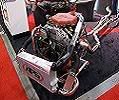
Basicly i'd like the setup to be like this^^ That is a VQ35de with a TT setup. I'm hoping that a VQ30det + T will be able to cope with higher boost more relyably due to being designed for forced induction, having forged internals, oil squirters and a nicer compression ratio.
As you can see, they only have one intake manifold, which is why i was asking if you can use the AFM on the cold side of the FMIC.
Thanks
Is that the typical speed sensor's that are usually found in the gearbox as a tailshaft output? The reason i ask is that the 6MT from the 350Z does not have this. It gets it's speed sensors from the ABS modules at the wheels.which you can fudge pretty easily with a simple square wave driven into the ECU
As a V6 in a small engine bay the shorter piping the better.AFM wise why not just join the two turbo inlets together and feed them through a Z32 AFM just like it's done on the twin turbo Z32?
Basicly i'd like the setup to be like this^^ That is a VQ35de with a TT setup. I'm hoping that a VQ30det + T will be able to cope with higher boost more relyably due to being designed for forced induction, having forged internals, oil squirters and a nicer compression ratio.
As you can see, they only have one intake manifold, which is why i was asking if you can use the AFM on the cold side of the FMIC.
Thanks
Most of the speed sensor inputs are the same. The sensor signal doesn't go direct to ECU. It normally goes through the speedo head or some other circuitry before going to the ECU. Dunno why I'm typing this - I've done it before. Lookee here:
http://www.plmsdevelopments.com/ssi.htm
I make a little module that goes between the speed sender and the ECU for when people do engine conversions and don't have the original speedo.
I now do a tiny little board that sits inside the ECU (not mentioned on my website) that just makes a simple square wave to keep the ECU happy. It makes the ECU read a constant speed. This isn't ideal but it stops the ECU from playing up because it doesn't have a speed signal at all. All the buggy guys use them.
You can run the AFM between IC and TB but they tend to get contiminated with oil mist from your turbo. So I don't recommend it. This can really mess up your AFM reading - even a little bit of oil can screw them up. If this causes the mixtures to lean out then it can lead to very bad things happening to your engine!
PL
-
gadget1382
- Posts: 6
- Joined: Fri Aug 29, 2008 2:10 pm
- Contact:
Side issue, I have a CA18det Auto. Runs the majority of the S13 loom. It's ok, is just missing the Pulse signal. Purely because the cluster wiring was removed. It works/shifts off the rpm signals from the Auto, but as soon as traction is lost, it goes into limp mode.I make a little module that goes between the speed sender and the ECU for when people do engine conversions and don't have the original speedo.
I assume if i just linked the wires up it woul not work. If that's the case I assume one of your units would solve that problem?
What are the ramifications of that? Does the ECU make allowances for anything as a result of the speed signal? If not then this would be a good quick fix for the VQ30det with a MT bolted to it.I now do a tiny little board that sits inside the ECU (not mentioned on my website) that just makes a simple square wave to keep the ECU happy. It makes the ECU read a constant speed. This isn't ideal but it stops the ECU from playing up because it doesn't have a speed signal at all. All the buggy guys use them.
Yes i understand that. (though though my limited knowledge it's more likely to make things rich) That was why i was enquiring as to the ability to have two AFM's. Splicing two off the one connector would be unlikely to be correct. I had read on here somewhere that a specific Power FC or SAFC would allow two to opperate, is this common practice or not as accurate for tuning?You can run the AFM between IC and TB but they tend to get contiminated with oil mist from your turbo. So I don't recommend it. This can really mess up your AFM reading - even a little bit of oil can screw them up. If this causes the mixtures to lean out then it can lead to very bad things happening to your engine!
You'll have to check the manual about the CA18. They may be different to SR20 (I deal primarily with SR20 stuff). They appear to use a reed switch + magnet arrangement in the speed sensor. SR's use a magnet/coil system.
Looks like CA's still send the speed sensor signal to the speedo head though so I suspect the speed signal going into the ECU would be same as for the SR (5V square wave). So one of my little in-ECU single speed square wave generator jiggers may do it.
Most ECU's just want a speed signal of some sort to keep them happy. This signal is used for stuff like holding a high idle until the car stops, not running aircon fans once above a certain speed etc. Which most engine conversion people don't care too much about.
What they do care about is their ECU going into limp mode or cutting out totally at WOT in 3rd gear (S13 SR20DE does this if the speed signal is missing).
I guess PFC would have 2 AFM inputs so it can run on a GTR. Not sure. I have minimal experience with them. I suspect that if you wanted to run 2 AFM's on your factory ECU then you'd need some sort of simple circuit that would take the 2 signals and average the two. On a very simplistic level you could probably just use 2 resistors of the same value to connect the outputs from the 2 AFM's and take the signal from the middle! Worth a try I guess. It's not like the two signals should vary much.
PL
-
gadget1382
- Posts: 6
- Joined: Fri Aug 29, 2008 2:10 pm
- Contact:
Sounds like a little more research is required... but a speed signal would be great. Just have to clarify that the CA18det ECU requires a 5V square wave and not a direct AC signal or otherwise.
I'll PM you if i need one.
As for the Intakes, halving the output and splicing together sounds like it could work. Though electrical circuitry was never prominent in my eng degree.
The other thing i just realised is the exhaust sensor. Would that work in a similar fashion to splitting the air intakes?