I will try it out.
boost control using nistune experiences anyone ?
Moderator: Matt
-
chris2712au
- Posts: 343
- Joined: Thu Jun 19, 2008 1:52 am
- Location: sydney australia
-
Legionnaire
- Posts: 125
- Joined: Fri Oct 03, 2008 5:45 am
- Location: Moscow, CFD, Russia
I know it is offtopic here, but I have to notice that those calculations can provide only rough estimation that needs to be refined later.
E.g. I tried to develop some 500HP from a 152 cid engine (meant to be RB25) and at 0.55 BSFC and 12.0:1 AFR at 7000. It states that mass flowrate required equals 55lb/min, which is quite right for 0.55 SFC, but 92% VE calls for 3.24 pressure ratio, which is not correct and can be easily disproved by dyno results (like ~500hp@1.4-1.5 bar boost <=> 2.4-2.5 PR which is fortunately much lower than calculated 3.24). The reason for this disparity is that volumetric efficiency is not fixed for every rpms and pressures. Since volumetric efficiency is ingested volume to atmosperic volume ratio, it obviously can be (and is) higher than 100% under boost due to pressure and density difference. I have seen a graph somewhere (supposedly created by garrett itself) that VE of engines boosted by Garrett's GT series turbos is ~115% for T28, 125% for T30 and so on. That also explains why bigger turbos make more power for the same mass flow rate.
Not so sure about factors affecting SFC, but i'm certain that it is not fixed either. Efficiency of combustion chamber and partly compression ratio play huge role here. BMW engines tend to be much more fuel efficient even boosted, like 0.49 lb/HP*hr instead of average 0.55. Water/meth injection, camshaft events, and/or very efficient intercooling can also change this figure significantly.
So the idea is to crate a 3D table of calculated flowrates on PR vs RPM vs VE axises, this can provide little more accurate data. To estimate VE you need torque and pressure ratio curves plotted against rpms. For calculations use formulas from Garrett, just like Chris suggested
Petros
Cheers,
Petros Katunian
Petros Katunian
-
chris2712au
- Posts: 343
- Joined: Thu Jun 19, 2008 1:52 am
- Location: sydney australia
good info...
guess VE is alot to do with flow.. and that can be optimised by cam timing and all kinds of things.. I havent investigated too far... just into the tech section and it started to get a little too involved so I made the calc instead of having to use a calculator and notepad.. if you had the VE table... for your setup... it is just so involved to figure it out... like your saying...
guess VE is alot to do with flow.. and that can be optimised by cam timing and all kinds of things.. I havent investigated too far... just into the tech section and it started to get a little too involved so I made the calc instead of having to use a calculator and notepad.. if you had the VE table... for your setup... it is just so involved to figure it out... like your saying...
-
Legionnaire
- Posts: 125
- Joined: Fri Oct 03, 2008 5:45 am
- Location: Moscow, CFD, Russia
To be more precise, VE has a lot to do with boost pressure required for engine to swallow X lbs or kgs of air. Estimated (typical for your engine in good tune) SFC then provides you the info that Y fuel is required to generate a horsepower. And at the last stage when this X airflow meets Y amount of fuel you adjust AFRs and other parameters trying to reach estimated SFC without compromising power and drivability.
For example diesel engines are MUCH more fuel efficient, they have SFCs like 0.34-0.39 and. But usually they target at 22:1 AFR, so their airflow requirements for the same power level are much higher than that of gasoline engines - btw thats why diesel turbos are so huge for their rated power levels.
All the above is a generalization, of course. SFC is engine speed, load, and tune dependent, and making power has much more in it than just cramming air and fuel into combustion chambers.
As for VE maps, I have made a VE table for stock cam and phasing RB25 neo a couple of years ago, I'll try to find it.
Petros
Cheers,
Petros Katunian
Petros Katunian
-
chris2712au
- Posts: 343
- Joined: Thu Jun 19, 2008 1:52 am
- Location: sydney australia
-
chris2712au
- Posts: 343
- Joined: Thu Jun 19, 2008 1:52 am
- Location: sydney australia
legionaire check this out..
I just picked up Corky Bell's "Maximum Boost" this week and started reading it. I'll share/steal some from him.
He defines Volumetric Efficiency as "the ratio of the number of molecules of air that actually get into a combustion chamber to the number of molecules in an equal volume at atmosperic pressure. For atmospheric engines, this ratio is almost always less than one. Supercharged engines are capable of operating at ratios greater than one."
And consider a turbo, a supercharger powered by a turbine.
A 100% volumetric efficient normally aspirated SR20DE would have an airflow rate of:
Airflow rate = (CID X RPM X .5 X Ev)/1728
CID(cubic inche displacement) = 2000cc X .061037 = 122 CID
RPM= 7000
.5 = constant for 4 stroke engines
Ev(Volumetric Efficiency)= 1.0
1728= converts cubic inches to cubic feet
So a 100% Ev SR20DE would be intaking 247 cubic feet per minute of air @ 7000 rpms.
For a boosted motor, Airflow = pressure ratio X basic engine cfm
Pressure ratio = (14.7 + boost)/14.7
So at 10 psi the pressure ratio would be 1.68. And the aiflow would be: 1.68 X 247 cfm = 415 cfm
That equation is simplified and just provides an estimate, because it assumes a turbo that is 100% efficient @ 10 psi @ 7000 rpms. But it does show how a turbo could produce a Ev>100%.
was posted on another site with..
Simple calibrate the MAF to grams per second on a flow bench, then divide by 4 cylinders and rpm..................how many grams flow into cylinder per revolution vs displacement = VE.
does this mean that nistune could log it given the correct data ?
then maybe you could predict what turbo gives you what fairly accurately ?
chris
-
Legionnaire
- Posts: 125
- Joined: Fri Oct 03, 2008 5:45 am
- Location: Moscow, CFD, Russia
Hey Chris
Corky has indeed provided some good guidelines with his effort in "Supercharged!" and "Maximum Boost", however not all the stuff there is quite correct. E.g. in chapter 9 on page 112 he states that the denser the AF mixture the slower the burn rate of it, which is definitely not so. Now I'm not trying to deny the fact that "Maximum Boost" does a very good job in explaining the idea of turbocharging and all principles applied, but you should be careful sometimes with calculations and small pieces of information - you may try some other books later and compare them to each other to separate facts from author's opinions.
I'm not sure what parameter do you suggest as a candidate for logging. Assuming it is VE, it is an interesting idea if you have voltage-to-mass flowrate conversion table for your MAF sensor. But you can't do it as per Corky's definition of VE, because he uses vague term for the numerator
Conclusion: you can calculate VE it two ways - using mass ratio(yes, I remember that efficiency is VOLUMETRIC but power is produced by mass, not by volume of air), or using volume ratio.
If you try to divide measured consumed air mass by mass of 2 liters of air, you need
for the numerator
1)AFM V->kg/sec conversion table
2)air speed estimation to calculate time required by measured portion of air to travel from AFM to engine and memory buffer for engine speeds (to calculate actual VE for that speed)
3)maybe I forgot smth else here
for the denominator
1)ambient pressue
2)ambient temperature
3)humidity
all the above - to calculate mass of 2 liters of air
if you want to calculate VE dividing consumed flow by 2 liters, you'll need
for the numerator
1)AFM V->kg/sec conversion table
2)ambient pressure
3)ambient temperature
4)humidity
2)-4) to convert measured mass to volume
5)yeah, all delays for air travelling from AFM to engine count here also
for the denominator - nothing, actually, we know that 2 liters are 2 liters. The aspect worth mentioning here is that under boost (either turbo, supercharger or resonance) engine will not consume its displacement volume of air per cycle but rather (displacement + chamber * amount of cylinders) volume. Dunno about SR20, but for RB25 Neo this is some 62cc * 6 = 0.36 liter, which is considerable.
So we can see that one way or the other, you need some additional sensors to do conversion calculations for either mass or volume. As far as I know there is a little amount of cars equipped by both T amb and Baro sensors and those that are usually use speed density sensing instead of mass airflow and they use ideal gas law for their calculations.
As for above formulas, they are good for giving you some approximate numbers, but you need more calculations based on real world data to make a conclusion that is worth logging.
As you can see, your result after applying the formula to SR20 (or any other 4 stroke IC piston SI engine for that matter) is measured in CFM -> volumetric flow rate. On the other hand you can see that all garrett compressor and turbine maps have lb/min on their X axis -> mass flowrate. To estimate power (and to provide accurate fuelling) you need to derive mass flowrate from volumetric flowrate. To do this you have to start with correction for density drop/rise, and this is very time consuming and hard to do part. At the very least you'll need to measure temperature at several points and have an idea as to where exactly on the compressor map you are for every engine state to calculate density and later mass flowrate.
It is often stated that 100hp roughly equals 150CFM or 10.5lb/min worth of air, but this is obviously gross simplification, because peal power is very SFC, CR, cam(-s) and after all tune dependant. E.g. you managed to push 45lb/min of air @1.7 pressure ratio into chambers at 5500rpm. Nice. Now it is time to make this air produce some torque, and here matter gets complicated.
Sorry for such a muddled, long and not very promising post. I was buying R34 GTR dash panel on yahoo.auctions while writing this.
Petros.
Corky has indeed provided some good guidelines with his effort in "Supercharged!" and "Maximum Boost", however not all the stuff there is quite correct. E.g. in chapter 9 on page 112 he states that the denser the AF mixture the slower the burn rate of it, which is definitely not so. Now I'm not trying to deny the fact that "Maximum Boost" does a very good job in explaining the idea of turbocharging and all principles applied, but you should be careful sometimes with calculations and small pieces of information - you may try some other books later and compare them to each other to separate facts from author's opinions.
I'm not sure what parameter do you suggest as a candidate for logging. Assuming it is VE, it is an interesting idea if you have voltage-to-mass flowrate conversion table for your MAF sensor. But you can't do it as per Corky's definition of VE, because he uses vague term for the numerator
- what is this? Looks like mass to me but hard to tell what "amount of molecules" really means here; and laterCorky Bell wrote:number of molecules of air that actually get into a combustion chamber
for denominator - this figure will vary for different ambient conditions (temperature and pressure to name few). In addition to that, we are really after oxygen in chambers, we don't really care about nitrogen and other atmospheric gases and vapours, this means that although VE will not change with humidity, oxygen containment, and therefore power, will.Corky Bell wrote:number of molecules in an equal volume at atmosperic pressure
Conclusion: you can calculate VE it two ways - using mass ratio(yes, I remember that efficiency is VOLUMETRIC but power is produced by mass, not by volume of air), or using volume ratio.
If you try to divide measured consumed air mass by mass of 2 liters of air, you need
for the numerator
1)AFM V->kg/sec conversion table
2)air speed estimation to calculate time required by measured portion of air to travel from AFM to engine and memory buffer for engine speeds (to calculate actual VE for that speed)
3)maybe I forgot smth else here
for the denominator
1)ambient pressue
2)ambient temperature
3)humidity
all the above - to calculate mass of 2 liters of air
if you want to calculate VE dividing consumed flow by 2 liters, you'll need
for the numerator
1)AFM V->kg/sec conversion table
2)ambient pressure
3)ambient temperature
4)humidity
2)-4) to convert measured mass to volume
5)yeah, all delays for air travelling from AFM to engine count here also
for the denominator - nothing, actually, we know that 2 liters are 2 liters. The aspect worth mentioning here is that under boost (either turbo, supercharger or resonance) engine will not consume its displacement volume of air per cycle but rather (displacement + chamber * amount of cylinders) volume. Dunno about SR20, but for RB25 Neo this is some 62cc * 6 = 0.36 liter, which is considerable.
So we can see that one way or the other, you need some additional sensors to do conversion calculations for either mass or volume. As far as I know there is a little amount of cars equipped by both T amb and Baro sensors and those that are usually use speed density sensing instead of mass airflow and they use ideal gas law for their calculations.
As for above formulas, they are good for giving you some approximate numbers, but you need more calculations based on real world data to make a conclusion that is worth logging.
As you can see, your result after applying the formula to SR20 (or any other 4 stroke IC piston SI engine for that matter) is measured in CFM -> volumetric flow rate. On the other hand you can see that all garrett compressor and turbine maps have lb/min on their X axis -> mass flowrate. To estimate power (and to provide accurate fuelling) you need to derive mass flowrate from volumetric flowrate. To do this you have to start with correction for density drop/rise, and this is very time consuming and hard to do part. At the very least you'll need to measure temperature at several points and have an idea as to where exactly on the compressor map you are for every engine state to calculate density and later mass flowrate.
It is often stated that 100hp roughly equals 150CFM or 10.5lb/min worth of air, but this is obviously gross simplification, because peal power is very SFC, CR, cam(-s) and after all tune dependant. E.g. you managed to push 45lb/min of air @1.7 pressure ratio into chambers at 5500rpm. Nice. Now it is time to make this air produce some torque, and here matter gets complicated.
Sorry for such a muddled, long and not very promising post. I was buying R34 GTR dash panel on yahoo.auctions while writing this.
Petros.
-
chris2712au
- Posts: 343
- Joined: Thu Jun 19, 2008 1:52 am
- Location: sydney australia
-
chris2712au
- Posts: 343
- Joined: Thu Jun 19, 2008 1:52 am
- Location: sydney australia
an email that I wrote to a colleague on here
The main problem that the system has well atleast as far as we know on the s15 is the fact that the boost table is only 2 dimensional.. meaning it will only give a response based on RPM and that the load on the engine is the main controller for the boost.. what happened to me is that you get creep.. this is the wastegate cracking open before it needs to be open and hence slowing the car from comming on boost... I ended up with a couple of tunes one for cruising and one for power... it is like when you floor the accelerator and boost rises fast you have to start bleeding the pressure earlier.. and when the boost comes on slower you can bleed it alot later..
I got spike from it.. not too bad but spike all the same..
so the trick is that the graph has to be smarter it is ok to have a setting proportional to load and RPM but it would be nice to have a setting that is like gain and measures how fast the boost is climbing and makes an extra response a little earlier to prevent the spike.. it would be like bleeding more air at the same rpm at less load.. and less air at more load..
however you can cheat by getting your boost signal closer to the source (compressor cover) so there is no delay and also getting a faster wastegate like an external...
-
chris2712au
- Posts: 343
- Joined: Thu Jun 19, 2008 1:52 am
- Location: sydney australia
this is what I envisaged
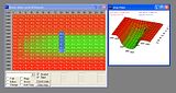
at low loads and rpm the boost signal from the manifold should not be enough to open the wastegate anyway so why not bleed it off just to make sure there is absolutely no creep in these low load low rpm areas and also in the low load transition area as there is not enough boost signal either to open actuator.... to get it boosting as quick as possible kind of makes the map look like an open ended bathtub... It would be so much easier if we could just read from a map sensor as you are actually measuring what you are trying to control.. this system is kind of like using tps and gear selection to calculate speed..
Looking at it from another angle is the there is a time delay to fill the actuator and open the wastegate especially when there is preload and mechanical linkages to think about.. with external this is less of a problem as they are bigger better flowing and direct.. this time delay needs to be taken into account as it is fixed.. and unfortunately the time it takes to come on boost is load dependant and changes..
-
skylinegtrhr
- Posts: 301
- Joined: Sat Jun 21, 2008 1:50 am
- Location: Croatia
- Contact:
I have one early 1994. S14 which have boost sensor before throttle body,chris2712au wrote:It would be so much easier if we could just read from a map sensor as you are actually measuring what you are trying to control.. this system is kind of like using tps and gear selection to calculate speed..
but is there possibility to read it?
And how precise is it at all?
-
skylinegtrhr
- Posts: 301
- Joined: Sat Jun 21, 2008 1:50 am
- Location: Croatia
- Contact:
Pete already explain that that is not good idea and I didn't see in real life good daily drive car with MAP ( I'm talking about tune mapped car with some standalone) as we have very big temperature and altitude range in our country.ge0ne wrote:Disabling MAF and having only MAP controlled maps would be great.
viewtopic.php?p=7561&highlight=afm+map#7561
or are You talking only about boost maps?
-
chris2712au
- Posts: 343
- Joined: Thu Jun 19, 2008 1:52 am
- Location: sydney australia
when it comes to sensing airflow you are more interested in the mass of air not the volume.. Mass Airflow Meters.. mass meaning weight of air.. this means it is taking into account the density of air all temps and altitudes.. but with MAP Manifold Absolute Pressure is takes only the pressure and then it needs to be corrected with a temp sensor.. so they can say 10psi @ 40deg = Xkgs of air.. but set at a certain efficiency..
map sensors always need tweaking to maximise your mods.. and need tweaking if anything minor changes as there is no give in the system.. however when it comes to boost control not Fuel it is ok just to use pressure and not correct it with temperature.. from what I have seen on the skyline ECU's they look to have the indexing done via the MAP sensor.. I think it is also doing the boost cut but I am not 100%
map sensors always need tweaking to maximise your mods.. and need tweaking if anything minor changes as there is no give in the system.. however when it comes to boost control not Fuel it is ok just to use pressure and not correct it with temperature.. from what I have seen on the skyline ECU's they look to have the indexing done via the MAP sensor.. I think it is also doing the boost cut but I am not 100%
Last edited by chris2712au on Sat Sep 26, 2009 10:37 pm, edited 1 time in total.