Hi,
I have a chipped z32 ecu. I am wanting to download the chipped bin file so I can use that as a base map for when I install Nistune onto the board. It is not allowing me to connect to consult however.
I can connect with my cable to blazt, ecutalk, etc. but not Nistune (or at least that is what it seems like). I am using a serial to usb cable for my consult connector but I don't think that should matter since ecutalk and blazt easily connect.
From my understanding all I should have to do is
1. open nistune and connect consult cable (ignition to on)
2. load adr file for z32
3. load image file
4. go to operations - consult download
5. save that file and use it for when I install the nistune board.
When I go to download I get a "only for use with standard factory consult" (something like that, going from memory). If I try syncing I'm told the drivers don't work.
In the bottom corner Nistune always says cannot connect to consult.
Thanks for any help. I just want to get this file so I can solder the board in!
Cannot consult download - connectivity issue
Moderator: Matt
???
I have my board in and works fine...downloaded other's maps.
I had a problem with ground at first, just checked ecu mounting bolts ( I also run a 5 point ground kit). The only difference I see is that you run serial port to USB. I don't know about those other programs...but, this is more about connecting I think. I have no klnowledge about serial to USB, but that is our only difference.
Hope it is running soon...
Need USB drivers.
If you buy PLMS USB cable (works with Nistune tuning software), it requires that you install the USB drivers from link below, before installing Nistune tuning software, etc (follow PDF installation guide, don't miss a step) -
http://www.plmsdevelopments.com/usb_drivers.htm
With PLMS consult cable, uninstall everything and install above USB drivers. Then install Nistune tuning software, etc and it should work.
Can click on "connect" button in Nistune tuning software, without connecting consult cable to car (only to laptop) and green light flashes on cable box part of PLMS cable to show cable / USB drivers work.
Well I got it to connect with the new cable. Downloaded my old tune.
Then I installed the daughterboard...and now I cannot connect again with anything. The car will start and idle but will not give me any codes via the flashing led (or obviously consult). I assume this is limp mode and I installed something wrong? I'm going to desolder and resolder the 4 wires I had to do.
Then I installed the daughterboard...and now I cannot connect again with anything. The car will start and idle but will not give me any codes via the flashing led (or obviously consult). I assume this is limp mode and I installed something wrong? I'm going to desolder and resolder the 4 wires I had to do.
Well redid the connections. Bolted the ecu all the way in to make sure it was grounded. Same issue as before. No connection to consult. My check engine light is on and every time I turn on the ignition the a/c fan turns on (never did that before installing nistune). As far as I can tell the ecu can communicate with the car but I can't communicate with the ecu (since it will start, albeit roughly). Which means I can't drive since the base tune is the wrong size injectors/etc.
I'm not sure what to do next :/
I'm not sure what to do next :/
What is the part number written on the Nistune board and the part number written on your ECU casing?
Its good that it works with the original chip installed, which means resocketing is good, but obviously a probem with the 4 pin connector
Check the connector plug pin 1 matches to the correct number on the ECU board, as for the rest of the wires
Also check if possible with multimeter buzzing rest of the wires to check connectivity to the board
with the board plugged into the connector check the A-D ends 'buzz' out to the board pins with the meter in continuity mode
you have the adaptor cable in the correct way and are using a compatible rom image in the board
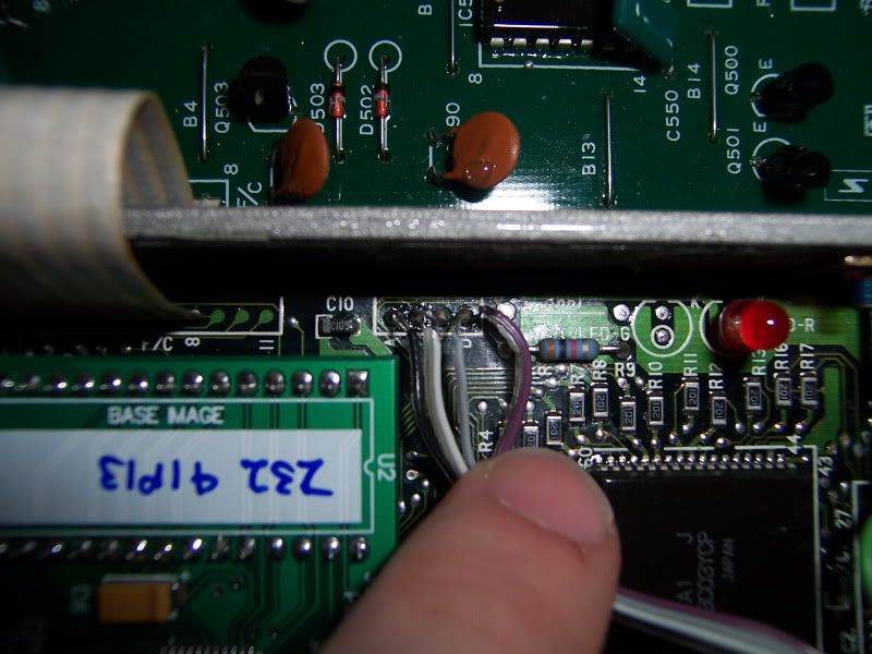
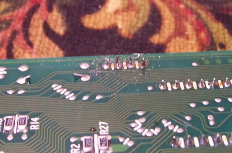
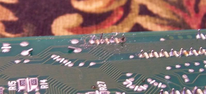
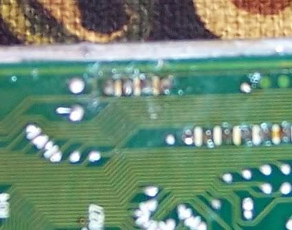
can you take some photos of the install for me to see and post them here?
the only other thing i can do is send another board over to try out, but I do test each one on the bench before posting out
you have the adaptor cable in the correct way and are using a compatible rom image in the board
can you take some photos of the install for me to see and post them here?
the only other thing i can do is send another board over to try out, but I do test each one on the bench before posting out
Well I took pics and they do make my solder work look really nasty...Not very visible to the eye but it sure looks bad in pictures. I also learned I have very bad picture taking skills....not easy to get that board into focus.
I'll check continuity after I post this. If you see any areas you can pinpoint that seem to cause problems I'd like to try and fix them. Otherwise I'll take the board to an electronics repair place on Monday and have it nicely soldered in there (and any other repair if necessary)
Thanks,
T
I'll check continuity after I post this. If you see any areas you can pinpoint that seem to cause problems I'd like to try and fix them. Otherwise I'll take the board to an electronics repair place on Monday and have it nicely soldered in there (and any other repair if necessary)
Thanks,
T