Cannot consult download - connectivity issue

Nistune topics related specifically to the 6303 cpu

Moderator: Matt

Matt
Site Admin
 

Posts: 8961
Joined: Sun Jan 29, 2006 1:45 am
Location: Adelaide, Australia
Contact:

Post by Matt »

Yikes! Just kidding...

Okay heat the connector pins from the bottom side and push the wire through with some tweezers slowly to get the plastic meeting the board at the top side

As for taking good photos... a fluro near by the ECU to provide good light and macro mode. PL has been giving me some tips for my next lot of photo taking to improve the pics in the Type 1 / Type 2 manuals 8)

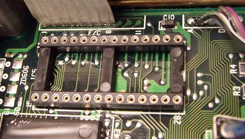
As for either of these suggestions wont fix the problem. So I have an Z32 in front of me now. Did you use a screwdriver or similar to remove the original EPROM?

Did you scratch / dent any of the tracks between the pin 1 - 28 . Look closely becuase if you did and kill one of these tracks even with a small cut then it may stop those CPU lines from working

Photo without the board installed near these pins would be nice. After that we will need to do a board exchange
treese88
 

Posts: 15
Joined: Sun Jan 24, 2010 1:42 am
Location: Central Florida (UCF)

Post by treese88 »

I'll pull them in up to the plastic (hopefully get a better solder connection). I'll also remove the board, though I am pretty sure that isn't the issue since I have tried the original chip twice and it has been fine. If none of that gets it working I'll take it over to an electronics repair shop to see what they think.

I know it is in both are interests not to have to try a different board...and I'm going to be so excited when I see "consult connected."

Thanks for the help Matt.
treese88
 

Posts: 15
Joined: Sun Jan 24, 2010 1:42 am
Location: Central Florida (UCF)

Post by treese88 »

Pulled the wires through and made the solders nicer. It still didn't work even with perfect continuity so I took it to an electronics repair shop and was told the solders were fine and none of the tracks were damaged...I was hoping for damage. Here are some pictures of board/etc. I noticed the pins on the chip and daughterboard are slightly different. Could this cause issue (sockets still look exactly the same)? The daughterboard comes out of the socket much easier than the chip, though it is still in there tight.

Specs on car (in case something could cause inconsistency with the burned rom)
-AT TT ECU (car is MT - from what I can tell the rom is a MT though so that shouldn't matter)
-AIV's deleted - I think that would just throw the check engine light and shouldn't cause limp mode.

For the mean time I'll be going back to the old chip so I can drive around again.

Image

Image

Image

Image

Image

Thanks,
T
Matt
Site Admin
 

Posts: 8961
Joined: Sun Jan 29, 2006 1:45 am
Location: Adelaide, Australia
Contact:

Post by Matt »

thanks for the pics. We will try another board and see how that goes. Email me your address and I'll get that posted through
Matt
Site Admin
 

Posts: 8961
Joined: Sun Jan 29, 2006 1:45 am
Location: Adelaide, Australia
Contact:

Post by Matt »

actually i've got the 41P14 image so will chuck that one in. we have used 41P13 in the past though no problems

you will find the ashspec tune is probably from a different (USDM) part number anyway

41Pxx series are JDM ECUs
Post Reply